When stalled, both brushed and brushless motors draw a lot of current and generate a large amount of heat. This heat can permanently damage a motor in a fraction of a second if not managed correctly. Locked-rotor stall data can be a useful tool when designing robot mechanisms that need to hold a mechanical load for a particular amount of time. It is useful to know the approximate time to failure depending on the applied load so that mechanisms can be successfully designed around these limitations.
The NEO Brushless Motor is different than other common brushed motors used in the FIRST Robotics Competition. Brushless motors offer higher efficiency and higher power density than brushed motors, however, they require a more complex control scheme to operate due to the fundamentally different motor technology. Sensors are built into the NEO Brushless Motor for use by the SPARK MAX to properly spin the motor, and is required for proper operation.
Constant Current vs. Constant Voltage
Locked-rotor stall data has been published for virtually every brushed DC motor in FRC in the form of Torque vs. Time at a particular constant applied voltage. This data is simple to understand and gives the user an idea of how long a particular voltage can be applied before the motor fails. While applied voltage is straightforward and sometimes the only variable that you can control (e.g with the original SPARK or Victor SPX), it isn’t as useful when you need to maintain a constant torque to hold a constant load.
Over time, when applying a constant voltage, motor current, and therefore motor torque, changes as the windings heat up. Additionally, voltage data cannot be used directly as a way to compare the survivability of different motors, especially the NEO Brushless Motor. This is due to the difference in construction, especially the winding resistance and torque constants of the different motors.
Holding a constant torque requires maintaining a constant current in the motor windings (or motor phases). Therefore, it is useful to know the time to failure of a motor at different currents rather than different voltages.
Locked-rotor Testing with SPARK MAX Smart Current Limit
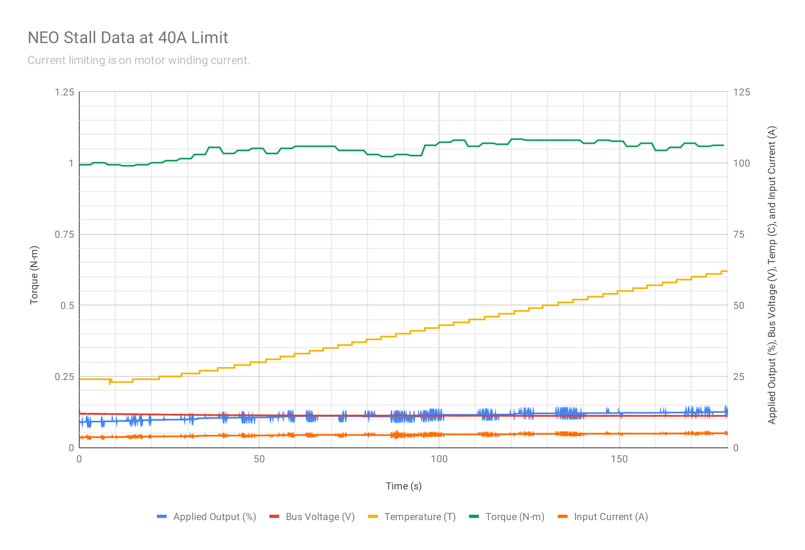
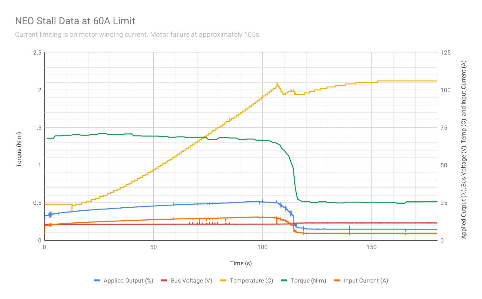
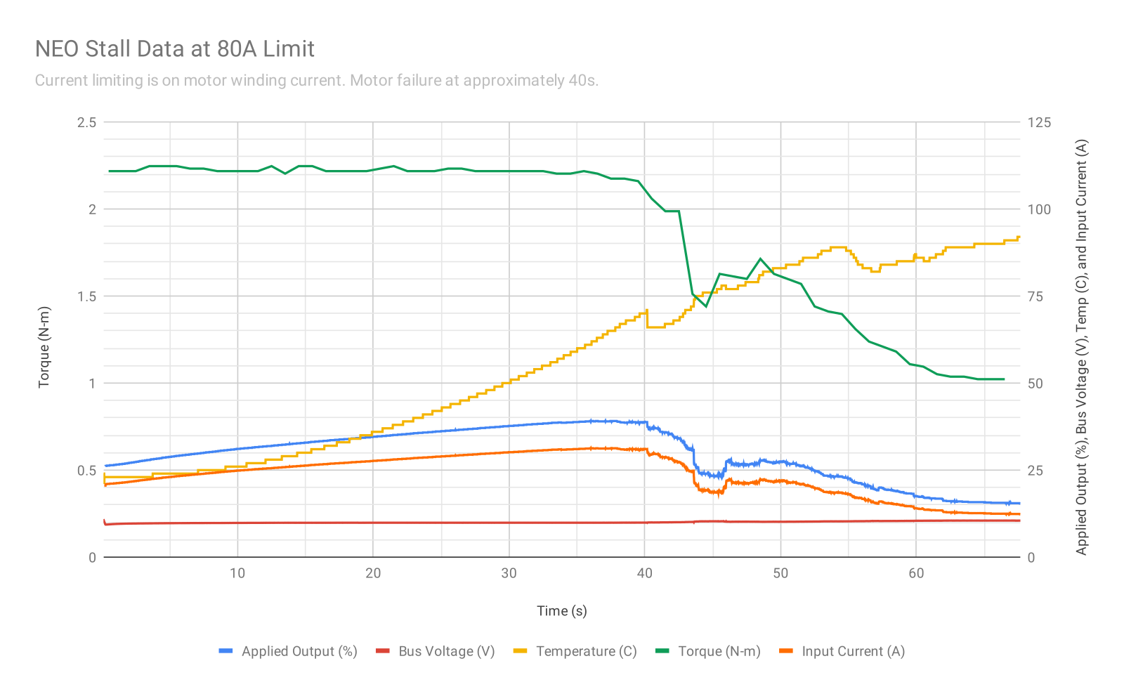
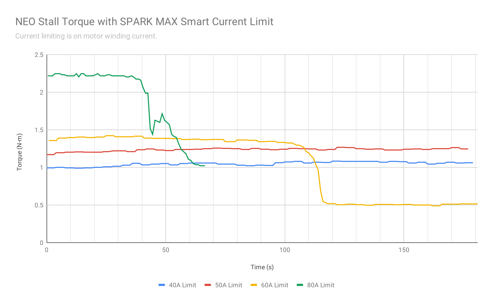
The SPARK MAX Motor Controller includes a Smart Current Limit feature that can adjust the applied output to the motor to maintain a constant phase current. Below you will find data at various current levels being maintained in the NEO Brushless Motor.
Please take the following into consideration when interpreting the data below:
- Average motor phase current (or winding current) is different than the average input current to the motor controller.
- Average Input Current = Average Phase Current x Duty Cycle
- Motor torque is proportional to phase current, not the input current. Therefore, it is important to control the phase current and not the input current.
- The torque values in the graphs are approximate and are measured using a digital torque wrench which includes an error up to ~5%. The intent is to show the point of failure and not the torque/current relationship. Please see the NEO Brushless Motor Datasheet for torque and current specifications.
- At higher current limits, the time-to-failure depends on many different factors. It is best practice to design mechanisms with considerable safety margin.
- Locked-rotor test setup:
- The NEO is mounted to an aluminum motor bracket at the face plate with the output shaft locked in place through a digital torque wrench.
- SPARK MAX is controlling the NEO and its Smart Current Limit is configured to the desired limit for the test. It is then commanded to go full-power while letting the Smart Current Limit adjust the applied output duty cycle as necessary to keep the phase current at the limit.
- Temperature measurements are read from the internal NEO temperature sensor. Temperature measurements lag behind the actual motor coil temperature due to the physical location on the motor. This data can also be used to approximate where limiting can be useful in user code based on the temperature measured.
- Power is provided by a 12V nominal, 18Ah, lead-acid battery through an FRC Power Distribution Panel with a 40A breaker. The breaker did not trip during any of the tests. Bus voltage is graphed to show the drop in battery voltage throughout the tests.
Data Summary
| NOTE! |
| The intent of this graph and the graphs below is to show an approximate time-to-failure at various current limits. Various factors can affect these times and, as always, mechanisms should be designed with considerable margin. These stall times are not guaranteed. |
Detailed Data at Each Limit


Raw Data
You can download the raw data in CSV format here: NEO Locked-rotor Testing Raw Data.

